CAN Bus Bit Timing Calculator
A calculator for CAN Bus nominal bit timing given your device capability, desired baud rate and desired sample point.
Scroll to Calculator ↓Overview of CAN Bit Timing
Controller Area Network (CAN) buses typically consist of multiple nodes, each operating with its own clock and associated error. Bus timing is defined at the bit level and includes a mechanism for synchronisation to account for oscillator tolerance between nodes. Each bit time is divided into a number of Time Quanta (TQ) defined by the device clock and prescaler. A single bit time is broken up into four sections defined in units of TQ as shown in the image below:
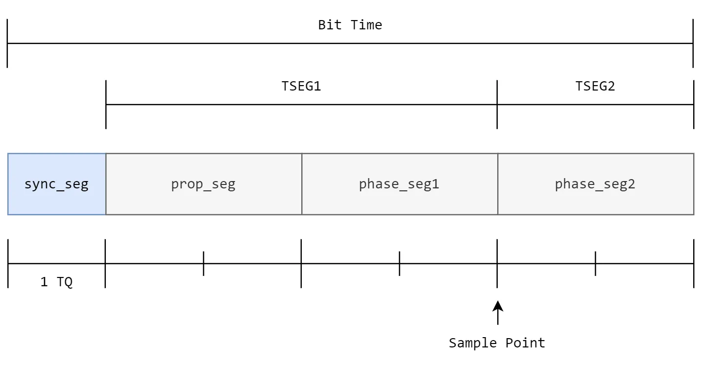
- Synchronisation Segment (sync_seg) - Fixed length of one time quanta. It allows nodes to synchronise to the start of the bit time.
- Propagation Segment (prop_seg) - Compensates for physical signal delay on the bus. It's sometimes combined with phase_seg1 and defined as TSEG1.
- Phase Buffer Segment 1 (phase_seg1) - May be lengthened during synchronisation. Sometimes combined with phase_seg1 and defined as TSEG1.
- Phase Buffer Segment 2 (phase_seg2) - May be shortened during synchronisation. Sometimes known as TSEG2.
In addition to these variables, the Synchronisation Jump Width (SJW) must be set. SJW defines the maximum number of TQ by which phase_seg1 and phase_seg2 may be lengthened/shortened to achieve synchronisation. It must not exceed the minimum of phase_seg1 and phase_seg2. Accurate nominal bit timing is essential for reliable communication and error-free data transmission within CAN bus networks. Understanding and configuring these parameters correctly ensures optimal bus performance and compatibility.
For more detail on CAN timing, consider reading the BOSCH CiA99 paper.
How the Calculator Works
The algorithm used in this CAN bit timing calculator iterates through all possible solutions using the provided constraints and selects the solution with the least baud error, least sample point error and maximum oscillator tolerance respectively. It will also prefer solutions with a lower prescaler where the solutions are equal, resulting in more Time Quanta (TQ). The source code for this calculator is available on GitHub.
The first, most outer loop of the algorithm loops through all possible prescalers. It then calculates the closest number of TQ that would be needed per CAN bit to achieve the desired baud rate using the following equation:
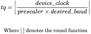
If the number of TQ is not within the device constraints, it is skipped and the next prescaler checked. If the number of TQ is within range, the baud error and maximum length of the propagation segment are calculated using the following equations:
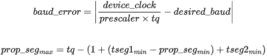
Once the baud error and maximum propagation segment value are known, the algorithm enters its inner loop and iterates over all possible propagation segment values from the given minimum constraint to the minimum of the calculated maximum propagation segment and the device maximum constraint.
Within the inner loop, the length of the other segments are calculated. The synchronisation segment is always 1 TQ long, leaving (tq - prop_seg - 1) time quanta for both phase segment 1 and phase segment 2. If the number of remaining TQ is even, both segments have the same value (half the remaining time quanta), else phase segment 2 shall equal one more than phase segment 1 to meet the desired total TQ. The resulting values of phase segment 1 and phase segment 2 are checked to ensure they fall within the device constraints.
After calculating the values of the phase segments, the maximum Sync Jump Width (SJW) is calculated as the minimum of the value of phase segment 1 and the maximum device constraint on SJW. At this point, all the information to calculate the oscillator tolerance is known and can be calculated using the following equations (see the BOSCH CiA99 paper for further details):
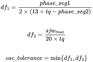
If the calculated oscillator tolerance is less than 0, the solution is not valid and the loop iteration is skipped. If it is valid, the sample point error is calculated using the equation below:

At this point, all information for the solution is known and it is checked to see if it is the current "best solution". To determine if the solution is the "best solution", the algorithm compares the current solution with the previous "best solution". It favors solutions with lower baud rate error, lower sample point error, larger oscillator tolerance, and lower prescalers (more TQ), preferring them in this order. Once all loop iterations have finished, the best possible solution using the above preference order will have been found. It is also possible no solution was found.
For further information on calculating CAN nominal bit timing, the BOSCH CiA99 paper may be helpful.
Interpreting the Results
Once your desired baud, desired sample rate and valid device constraints are provided, clicking the "Calculate Best Parameters" button will apply the above algorithm to calculate the parameters required to configure your device. The list below details each of the results shown in the "Calculator Output" panel.
- Baud Rate - The actual baud rate that is achieved using the parameters in this solution.
- Baud Rate Error - The baud rate error, calculated as the difference between the desired baud rate and the actual baud rate that is achieved using the parameters in this solution.
- Sample Point - The actual sample point that is achieved using the parameters in this solution.
- Sample Point Error - The sample point error, calculated as the difference between the desired sample point and the actual sample point that is achieved using the parameters in this solution.
- Oscillator Tolerance - The maximum allowable oscillator tolerance for nodes using the parameters in this solution.
- Max Prop Delay - The maximum total propagation delay including propagation delay.
- Total Time Quanta - The total number of time quanta in the solution.
- Prescaler (BRP) - The prescaler chosen for this solution.
- TSEG1 - The value of TSEG1 for this solution. The value in the output panel is expressed as <propagation segment> + <phase segment 1> (<total>).
- TSEG2 - The value of TSEG2 for this solution.
- Max SJW - The maximum value that SJW can be set to in this solution.